HYDRAULIC PIPE SIMULATION NETWORK MODELING – A CASE STUDY
ACW PUMPS HYDRUALIC MODEL
Gist
- Auxiliary Cooling Water (ACW) Pumps caters cooling water for DG, Lube Oil Coolers, STG Coolers, Control Room AC Units, BFPs, Air Compressors etc.
- There are 4 fours of centrifugal pumps are installed to cater cooling water for all these auxiliary users.
- ACW 1 & 2 are connected in a common header is designed to deliver flow rate of 750 m3/h against the head of 45 mWC.
- ACW 3 & 4 are connected in a common header is designed to deliver flow rate of 500 m3/h against the head of 45 mWC.
- These two pumping circuits are connected in common header from a 4’’ line near to STG lube oil cooler.
- Normally ACW 1 & 3 are operated in parallel to cater water flow rate for all these 11 no’s of auxiliary users.
Performance Study on ACW Pumps
| Design Details / Pump Identification |
Units |
ACW 1 |
ACW 3 |
Combined |
| Measured Flow rate |
m3/h |
675 |
80 |
755 |
| Suction pressure |
kg/cm2 |
0.25 |
0.25 |
0.25 |
| Discharge pressure |
kg/cm2 |
46.5 |
46.5 |
46.5 |
| Measured total Head |
m |
44 |
44 |
44 |
| Measured power |
kW |
104 |
38.9 |
142.9 |
| Pump Operating efficiency |
% |
77.8 |
24.6 |
63.3 |
Situational Analysis
- It is obvious pressure mismatch due to operating different duty pumps in parallel, which results in throttling effect of ACW 1 on ACW 3.
- ACW 3 is performing very inefficiently due to this operating scenario. Hence parallel operations of ACW 1 and ACW 3 should be avoided.
ACW3 be closed and with proposed network modification, ACW1 alone would cater the requirement – more than Rs 20 Lakhs savings.
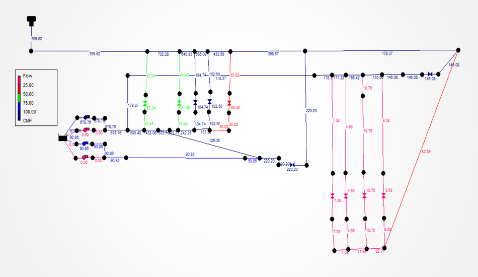
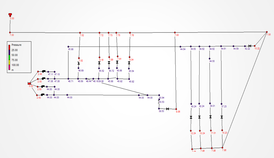
ACW 1 & 3 - BASE CASE MODEL – Flow Profile
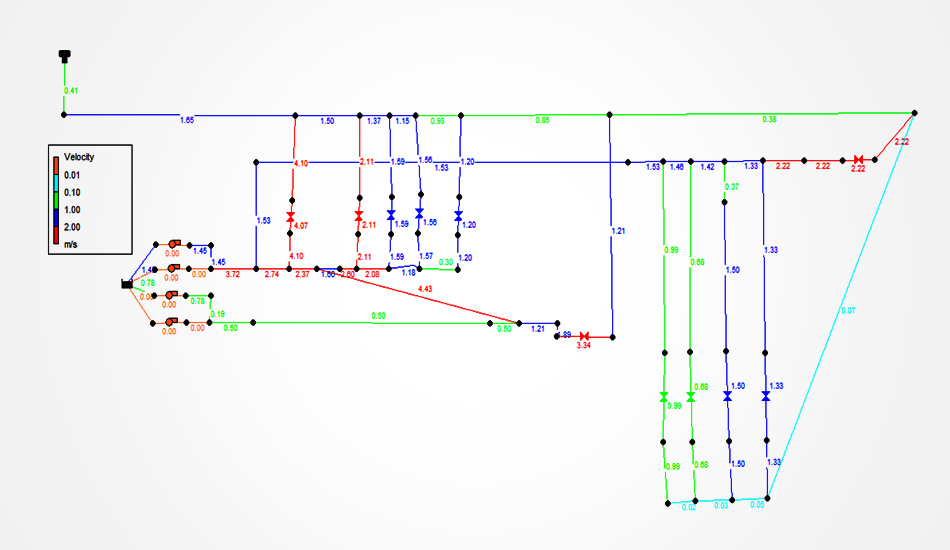
ACW 1 & 3 - BASE CASE MODEL – Velocity Profile
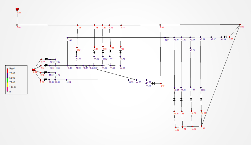
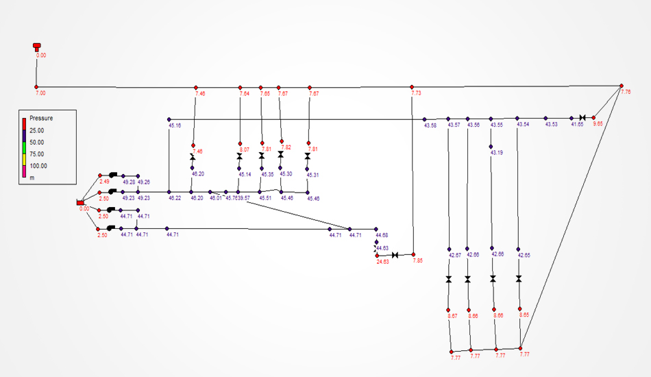
ACW 1 & 3 - BASE CASE MODEL – Pressure Profile
Major Observations
- 10’’ Main Header has a pressure drop of 3.2 mWC
- Also 2’’ Lines has a pressure drop of minimum 4 mWC
ACW 1 - CFB & AFBC 4’’ Line Modification + DG Valve Closed + ACW 3 Off – Flow Profile
Pump in Operation – ACW 1
Total Flow – 668 m3/h
Total Head – 46.8 mWC
Users like STG Lube Oil Cooler, Control Room AC and CFBC/AFBC auxiliaries has to be throttled to maintain flow balance
ACW 1 - CFB & AFBC 4’’ Line Modification + DG Valve Closed + ACW 3 Off – Pressure Profile
Pressure drop has been reduced to 1 mWC after throttling as per requirement
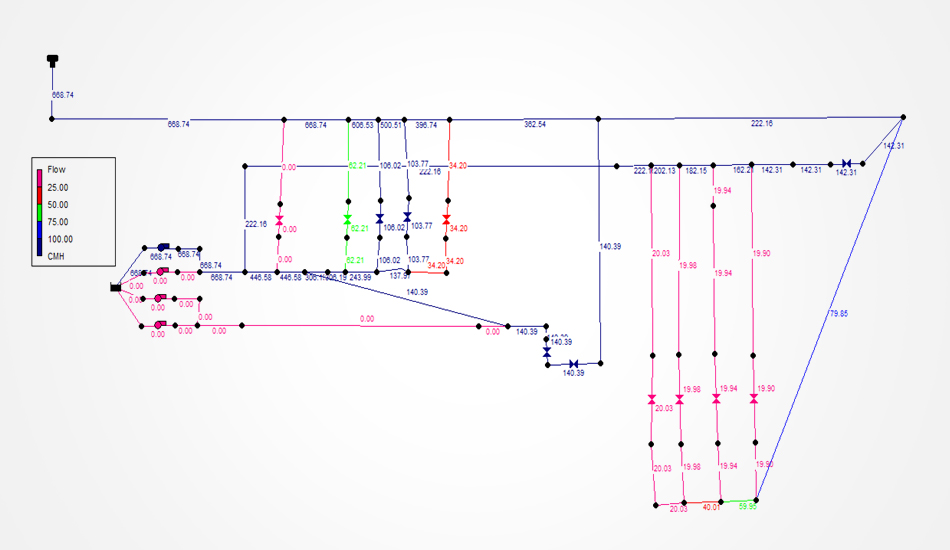
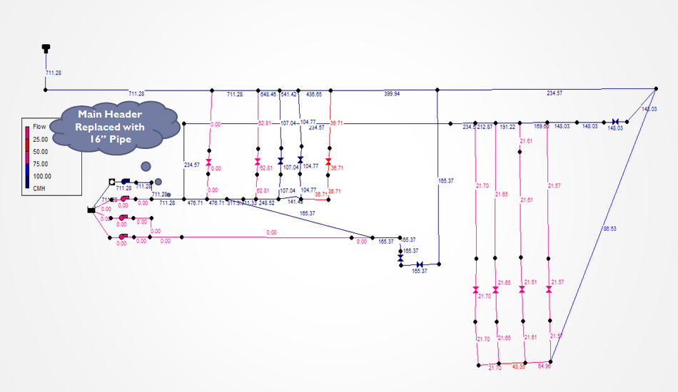
ACW 1 – 16’’ Main Header + CFB & AFBC 4’’ Line Modification + DG Valve Closed + ACW 3 Off – Flow Profile
Pump in Operation – ACW 1
Total Flow – 711 m3/h
Total Head – 44.7 mWC
Users like STG Lube Oil Cooler, Control Room AC and CFBC/AFBC auxiliaries has to be throttled to maintain flow balance
ACW 1 – 16’’ Main Header + CFB & AFBC 4’’ Line Modification + DG Valve Closed + ACW 3 Off – Pressure Profile
Pressure drop has been reduced to 0.38 mWC and velocity reduced to 1.5 m/s after throttling as per user requirement
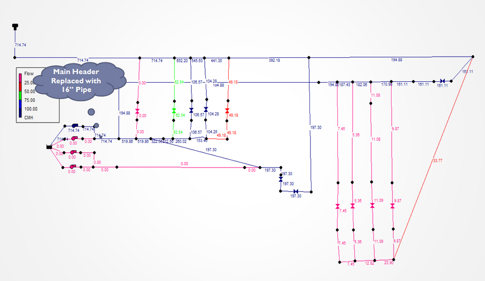
ACW 1 – 16’’ Main Header Line Modification + DG Valve Closed + ACW 3 Off – Flow Profile
Pump in Operation – ACW 1
Total Flow – 714 m3/h
Total Head – 44.5 mWC
Users like STG Lube Oil Cooler, and Control Room AC has to be throttled to maintain flow balance
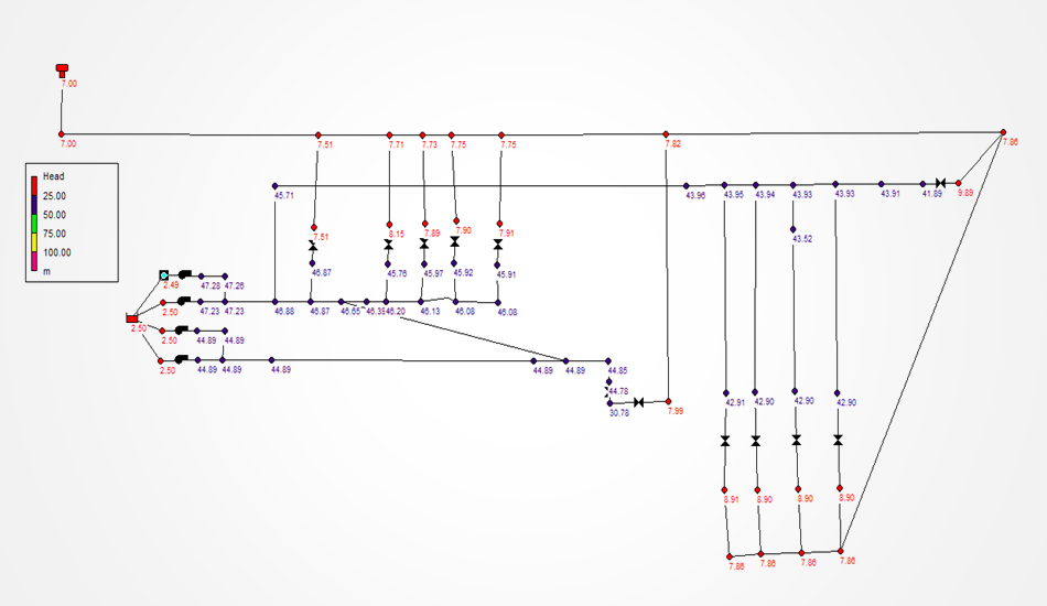
ACW 1 – 16’’ Main Header Line Modification + DG Valve Closed + ACW 3 Off – Pressure Profile
Pressure drop has been reduced to 0.38 mWC and velocity reduced to 1.5 m/s after throttling as per user requirement
Summary – ACW Hydraulic Network Analysis
| Condition |
Pumps Operated |
Flow Rate Delivered
m3/h |
Total Head Delivered
mWC |
Observations & Comments |
| Base Condition |
ACW 1 & 3 |
755 |
46.5 |
- Pressure drop of 3 to 4mWC in 10’’ Main Header and 2 ‘’ CFBC Line – Flow
- Starvation in CFBC 2’’ users
- Inefficient operation of ACW 3
|
| DG Closed + ACW 3 Off + 4’’ Line Replacement |
ACW 1 |
668 |
46.5 |
- Pressure drop reduced to 1 mWC in CFBC Users
- Overall flow got reduced
- Pressure drop of 4 mWC in 10’’ Main Header
|
| DG Closed + ACW 3 Off + 4’’ Line & 16’’ Line Replacement |
ACW 1 |
711 |
44.3 |
- Pressure drop reduced to 1 mWC main header
- DG Closed
- Flow shall be balanced by minimal throttling
|
| DG Closed + ACW 3 Off + 16’’ Header Line Replacement |
ACW 1 |
714 |
44.5 |
- Pressure drop reduced to 1 mWC main header
- DG Closed
- Flow shall be balanced by minimal throttling
- Flow starvation in CFBC 2’’ Line
|
Recommended Case – Saves 39 kW Power of ACW 3 with higher flow rate